IND-MOD-IO88
Electrical Safety
Risk of Electric Shock
The IND-MOD-IO88 is intended for use with industrial control systems. Incorrect installation or wiring may result in electric shock, equipment damage, or personal injury.
- Disconnect all power sources before installing or servicing the module.
- Verify that the power supply is turned off before making or modifying any wiring connections.
- Never touch exposed conductors while the system is energized.
Qualified Personnel Only
Installation, commissioning, and maintenance of this product must only be performed by qualified personnel familiar with industrial electrical systems and local electrical safety regulations.
Observe Voltage Ratings
Ensure that all input voltages, output loads, and power supply connections remain within the specifications provided in this manual. Exceeding the maximum ratings may permanently damage the module.
Wiring
- Use appropriately sized wires and tighten terminal screws securely.
- Verify wiring polarity before applying power.
- Keep signal wiring separate from high-voltage or high-current cables to reduce electrical noise.
Regulatory Compliance
Follow all applicable local electrical codes and safety standards when installing and operating the IND-MOD-IO88.
Introduction
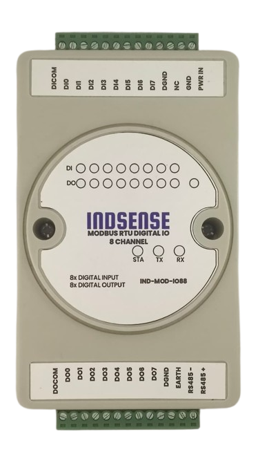
The IND-MOD-IO88 is a compact industrial Modbus RTU 8-channel I/O Module designed to simplify the integration of digital inputs and outputs into PLC, SCADA, HMI, and Industrial IoT systems. It communicates over the industry-standard RS-485 interface using the Modbus RTU protocol, ensuring reliable interoperability with a wide range of industrial automation equipment.
The module provides 8 opto-isolated digital inputs and 8 opto-isolated digital outputs, making it suitable for monitoring field devices such as push buttons, limit switches, proximity sensors, and relay contacts, while simultaneously controlling loads including relays, contactors, indicator lamps, solenoid valves, and other industrial actuators.
Designed for demanding industrial environments, the IND-MOD-IO88 supports both dry-contact and wet-contact (up to 24 VDC) digital inputs (NPN or PNP) with built-in bidirectional optocoupler and 8 Digital Outputs supports upto 40V, open-drain output, output load 500mA/channel(MAX) allowing seamless integration with a wide variety of sensors and control devices. The robust RS-485 communication interface enables reliable long-distance communication in electrically noisy environments.
Whether used as a distributed remote I/O module, a PLC expansion module, or an interface between field devices and Industrial IoT gateways, the IND-MOD-IO88 offers a cost-effective, reliable, and easy-to-deploy solution for industrial automation applications.
Key Features
- 8 opto-isolated digital inputs
- Supports both dry-contact and wet-contact inputs (up to 24 VDC)
- 8 opto-isolated digital outputs for controlling external loads
- RS-485 communication with Modbus RTU protocol
- Compatible with PLCs, HMIs, SCADA systems, and Industrial IoT gateways
- Long-distance, noise-immune industrial communication
- Compact DIN-rail mount enclosure
- Easy configuration and integration into existing Modbus networks
Typical Applications
- PLC I/O expansion
- Remote monitoring and control
- Factory automation
- Process automation
- Building management systems (BMS)
- Water and wastewater treatment
- Energy monitoring and control
- Industrial IoT and edge gateway applications
Technical Specifications
| Parameter | Specification |
|---|---|
| Communication Interface | RS-485 |
| Protocol | Modbus RTU (Standard Modbus RTU Protocol) |
| Supported Baud Rates | 4800, 9600, 19200, 38400, 57600, 115200, 128000, 256000 bps |
| Default Communication Settings | 9600 bps, 8 Data Bits, No Parity, 1 Stop Bit (8-N-1) |
| Power Supply | 7–28 VDC |
| Digital Inputs | 8 Channels |
| Input Voltage Range | 5–24 VDC |
| Input Type | Supports Dry Contact, NPN (Sinking), and PNP (Sourcing) Inputs |
| Input Isolation | Built-in Bidirectional Optocoupler Isolation |
| Digital Outputs | 8 Channels |
| Output Type | Open-Drain (Low-Side Switching) |
| Output Voltage Range | 5–40 VDC |
| Maximum Output Current | 500 mA per Channel (Maximum) |
| Modbus Slave Address | Configurable from 1 to 255 |
| Default Slave Address | 1 (0x01) |
Wiring
Terminal Assignment
| Terminal | Description | Terminal | Description |
|---|---|---|---|
| PWR IN | Power Supply Positive (+) | RS485+ | RS-485 Data A |
| GND | Power Supply Ground (-) | RS485- | RS-485 Data B |
| NC | Not Connected | EARTH | RS-485 Shield / Earth Ground |
| DGND | Signal Ground | DGND | Signal Ground |
| DI7 | Digital Input Channel 8 | DO7 | Digital Output Channel 8 |
| DI6 | Digital Input Channel 7 | DO6 | Digital Output Channel 7 |
| DI5 | Digital Input Channel 6 | DO5 | Digital Output Channel 6 |
| DI4 | Digital Input Channel 5 | DO4 | Digital Output Channel 5 |
| DI3 | Digital Input Channel 4 | DO3 | Digital Output Channel 4 |
| DI2 | Digital Input Channel 3 | DO2 | Digital Output Channel 3 |
| DI1 | Digital Input Channel 2 | DO1 | Digital Output Channel 2 |
| DI0 | Digital Input Channel 1 | DO0 | Digital Output Channel 1 |
| DI COM | Common Terminal for Digital Inputs | DO COM | Common Terminal for Digital Outputs |
Digital Input Wiring
The IND-MOD-IO88 supports three types of digital input connections:
- Dry Contact (Passive Input)
- NPN Sensor (Sinking Input)
- PNP Sensor (Sourcing Input)
DI COM Configuration
The DI COM terminal determines how the digital inputs operate.
| DI COM Connection | Input Mode |
|---|---|
| Not Connected | Dry Contact (Passive) Input |
| Connected to +V | NPN (Low-Level Active) Input |
| Connected to GND | PNP (High-Level Active) Input |
Note
The digital input voltage range is 5–24 VDC.
Digital Output Wiring
The digital outputs are Open-Drain (Low-Side Switching) outputs.
Connect DO COM to the positive terminal of the output power supply.
The output load should be connected between DO COM (+V) and the corresponding DOx output.
Warning
Each digital output can sink up to 500 mA maximum. Exceeding this rating may permanently damage the output driver.
RS-485 Wiring
| Terminal | Description |
|---|---|
| RS485+ | RS-485 Data A |
| RS485- | RS-485 Data B |
| EARTH | Cable Shield / Earth Ground (Recommended) |
Tip
- Use twisted-pair cable for RS-485 communication.
- Connect the cable shield to EARTH at one point only.
- Terminate both ends of the RS-485 bus with 120 Ω resistors when required.
- Avoid running RS-485 cables alongside high-voltage or high-current wiring.
Power Supply
| Terminal | Description |
|---|---|
| PWR IN | Positive Supply (7-28V) |
| GND | Negative Supply |
Warning
Verify the power supply polarity before powering the module. Reverse polarity may damage the device.
Operation Protocol
Function Code
| Function Code | Description | Note |
|---|---|---|
| 01 | Read Coil Status | Read digital output status |
| 02 | Read Discrete Inputs | Read digital input status |
| 03 | Read Holding Registers | Read device configuration parameters |
| 05 | Write Single Coil | Control a single output |
| 06 | Write Single Holding Register | Write device configuration |
| 0F | Write Multiple Coils | Control multiple outputs |
| 10 | Write Multiple Registers | Write multiple device configuration parameters |
Register Address
| Address (HEX) | Description | Register Value | Access | Function Code |
|---|---|---|---|---|
| 0x0000 .... 0x0007 |
Digital Ouput from DO0 to DO7 | 0x0000 = OFF 0xFF00 = ON |
Read/Write | 0x01, 0x05, 0x0F |
| 1x0000 .... 1x0007 |
Digital Input from DI0 to DI7 | 0 = OFF 1 = ON |
Read | 0x02 |
| 4x0000 | Modbus Slave Address | 1 ~ 247 | Read/Write | 0x03, 0x06, 0x10 |
| 4x0001 | Baud Rate | See Baud Rate Table | Read/Write | 0x03, 0x06, 0x10 |
Note
Function Code 0x0F (Write Multiple Coils) uses the same starting addresses (0x0000–0x0007) but writes multiple coil states in a single Modbus request.
Baudrate Table
| Baudrate | Register Value |
|---|---|
| 4800 | 0 |
| 9600 (Default) | 1 |
| 19200 | 2 |
| 38400 | 3 |
| 57600 | 4 |
| 115200 | 5 |
| 128000 | 6 |
| 256000 | 7 |
Modbus Communication Examples
The examples below assume the module is operating at its default Slave Address (0x01). All data frames are represented in Hexadecimal (HEX).
Understanding the Frame Structure
Every Modbus RTU frame follows a standard structure:
[Slave Address] [Function Code] [Data/Address bytes...] [CRC Low] [CRC High]
0x01: Read Coil Status (Read Digital Outputs)
Used to read the current ON/OFF status of the digital outputs (DO0 to DO7).
Example: Read the status of all 8 digital outputs (Starting address 0x0000, Quantity 8).
- Request Frame:
01 01 00 00 00 08 3D CC 01: Slave Address01: Function Code00 00: Starting Address (DO0)00 08: Quantity of Coils to read (8)-
3D CC: CRC16 -
Response Frame:
01 01 01 05 91 8B 01: Slave Address01: Function Code01: Byte Count (1 byte returned)05: Data (0x05= Binary00000101, meaning DO0 and DO2 are ON, the rest are OFF)91 8B: CRC16
0x02: Read Discrete Inputs (Read Digital Inputs)
Used to read the current state of the digital inputs (DI0 to DI7).
Example: Read the status of all 8 digital inputs (Starting address 0x0000, Quantity 8).
- Request Frame:
01 02 00 00 00 08 79 CC 01: Slave Address02: Function Code00 00: Starting Address (DI0)00 08: Quantity of Inputs to read (8)-
79 CC: CRC16 -
Response Frame:
01 02 01 03 E1 89 01: Slave Address02: Function Code01: Byte Count03: Data (0x03= Binary00000011, meaning DI0 and DI1 are currently triggered)E1 89: CRC16
0x03: Read Holding Registers (Read Configuration)
Used to read the device's configuration parameters, such as the Slave Address and Baud Rate.
(Note: When querying Modbus over the wire, the 4x prefix is omitted; address 4x0000 is transmitted as 0x0000).
Example: Read both the Slave Address and Baud Rate (Starting address 0x0000, Quantity 2).
- Request Frame:
01 03 00 00 00 02 C4 0B 01: Slave Address03: Function Code00 00: Starting Address (Slave Address Register)00 02: Quantity of Registers to read (2)-
C4 0B: CRC16 -
Response Frame:
01 03 04 00 01 00 01 6B F3 01: Slave Address03: Function Code04: Byte Count (2 registers = 4 bytes)00 01: Data 1 (Slave Address = 1)00 01: Data 2 (Baud Rate = 1, corresponding to 9600 bps)6B F3: CRC16
0x05: Write Single Coil (Control a Single Output)
Used to turn a single digital output ON or OFF. According to the standard Modbus RTU protocol, 0xFF00 turns the output ON, and 0x0000 turns it OFF.
Example: Turn ON Digital Output 1 (DO0, Address 0x0000).
- Request Frame:
01 05 00 00 FF 00 8C 3A 01: Slave Address05: Function Code00 00: Register Address (DO0)FF 00: Data (ON)-
8C 3A: CRC16 -
Response Frame:
01 05 00 00 FF 00 8C 3A(The device perfectly echoes the request upon success)
0x06: Write Single Holding Register (Change Configuration)
Used to write configuration parameters, such as changing the Slave Address or Baud Rate.
Example: Change the Baud Rate to 115200 bps (Register 0x0001, Value 5).
- Request Frame:
01 06 00 01 00 05 18 09 01: Slave Address06: Function Code00 01: Register Address (Baud Rate)00 05: Data Value (5= 115200 from the Baudrate Table)-
18 09: CRC16 -
Response Frame:
01 06 00 01 00 05 18 09(The device echoes the request upon success)
Warning
A power cycle or module reboot may be required before the new Baud Rate or Slave Address takes effect.
0x0F: Write Multiple Coils (Control Multiple Outputs)
Used to set the ON/OFF status of several digital outputs simultaneously in a single command.
Example: Turn ON DO0, DO1, and DO2, and turn OFF DO3 through DO7.
- Request Frame:
01 0F 00 00 00 08 01 07 3E 95 01: Slave Address0F: Function Code00 00: Starting Address (DO0)00 08: Quantity of Coils (8)01: Byte Count (1 byte of data to follow)07: Data (0x07= Binary00000111, meaning DO0, DO1, DO2 are ON)-
3E 95: CRC16 -
Response Frame:
01 0F 00 00 00 08 54 0D 01: Slave Address0F: Function Code00 00: Starting Address00 08: Quantity of Coils written54 0D: CRC16